
- Wuhan Yuli Automation Technology Co., Ltd
-
Wuhan, Hubei, China
- Main products: DCS, PLC, frequency converter, positioner
-
 peter
Hi there! Welcome to my shop. Let me know if you have any questions.
peter
Hi there! Welcome to my shop. Let me know if you have any questions.
Your message has exceeded the limit.
Carlo Gavazzi What are the common faults of gateway SD2DUG24?
2025-08-04 10:32:44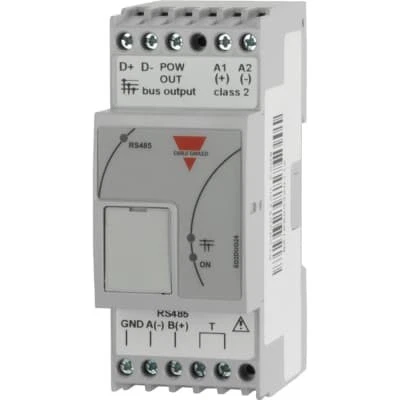
The Carlo Gateway SD2DUG24 is a common Modbus RTU to M-Bus gateway, which is mainly used to collect and convert the data of such meters as Carlo Gateway EM24/ET112 (through M-Bus) to the Modbus RTU network (such as PLC and SCADA system). This equipment is stable, but as with all industrial equipment, some common failures may occur.
The following are some common faults of SD2DUG24 gateway and their possible causes and troubleshooting directions:
Modbus RTU communication failure (unable to communicate with PLC/SCADA):
Phenomenon: PLC/SCADA cannot read gateway data, Modbus request timeout or no response.
Possible causes:
Wiring error: A/B wire is inversely connected (Modbus RTU is RS-485 with polarity requirements), shielding layer is not grounded or poorly grounded, terminal resistance is missing (required for long distance or bus terminal).
Mismatch of baud rate/data bit/stop bit/check bit: Modbus serial port parameters (baud rate, data bit, stop bit and check) of gateway must be completely consistent with master station (PLC/SCADA).
Modbus address conflict: the slave address of the gateway on the Modbus network conflicts with other devices.
Serial port damage: physical damage (lightning strike, surge, short circuit, etc.) of RS-485 interface of gateway or master station.
Cable quality problem/too long/interference: Non-pair shielded wire is used, cable length exceeds RS-485 specification (generally<1200m), close to strong current or frequency converter and other interference sources.
Inadequate power supply or interference introduced through power supply: unstable 24V power supply or loud noise.
M-Bus communication failure (meter data cannot be read):
Phenomenon: The gateway cannot read the meter data connected to its M-Bus, and the gateway indicator light (such as M-Bus activity light) does not respond.
Possible causes:
Incorrect wiring/polarity: M-Bus two-wire system has polarity requirements (L -/M - and L+/M+). Reversed connection will cause communication failure. The shielding layer is not grounded.
Missing terminal resistance: terminal resistance (usually 100-330 Ω) shall be installed at the end of M-Bus bus.
Meter address configuration error: M-Bus address of meter is not correctly added or address input error occurs in gateway configuration software.
Meter not initialized properly/not in scan list: newly added meter needs to be scanned in configuration software or added manually.
M-Bus Overload: The number of connected devices or bus length exceeds the M-Bus specification limits (number of devices, distance, wire diameter). SD2DUG24 supports a certain number of equipment (see the manual for details, usually dozens of sets), and the bus length is also limited (usually hundreds of meters to kilometers, depending on the wire diameter).
M-Bus power shortage: the gateway provides power for M-Bus. If too many meters are connected or the bus is too long, the voltage drop may be too low to drive all meter communications. Bus terminal voltage needs to be checked (should be within M-Bus specification e.g. 12V - 42V).
Single meter fault: a meter fault or wiring short circuit may collapse the entire M-Bus bus.
M-Bus port damage: physical damage of M-Bus interface of gateway.
Power failure:
Phenomenon: The gateway has no indicator light on and no response at all.
Possible causes:
Incorrect supply voltage: 24V DC power supply is not provided, or the supplied voltage is out of range (if AC power supply is connected).
Reversed polarity of power supply: 24V+and 0V/GND reversed.
Inadequate power supply: the power supply cannot provide the current required by the gateway itself and its M-Bus load.
Open circuit or poor contact of power line: loose terminal or broken cable.
Damage of internal power circuit: internal damage caused by surge, overvoltage and short circuit.
Configuration error/data mapping problem:
Phenomenon: Modbus communication is normal (PLC can read gateway response), but the read data values are all 0, 65535 (0xFFFF) or obviously wrong values, or the expected register cannot be read.
Possible causes:
Meter Modbus Mapping Address Configuration Error: The meter data is not properly configured to map to the start address and data type of the Modbus registers in the Gateway Configuration Software. The gateway needs to know which data of the meter (e.g. total active power) is mapped to which address of the Modbus register.
Inactive data point: in the configuration, the required meter data point (such as voltage and current) is not checked and enabled.
Incorrect polling interval setting: The gateway polling M-Bus meter interval is set too long.
Meter register address understanding error: The register address entered in the configuration software is inconsistent with the Modbus address defined in the meter manual (note whether decimal or hexadecimal, including offset).
Firmware Version Compatibility Issue: Gateway firmware or meter firmware version is older and may have known data mapping issues or Bugs.
Equipment failure:
Phenomenon: after removing all external factors (power supply, wiring, configuration), the equipment still cannot work properly, or intermittent crash, reset, etc.
Possible causes:
Hardware failure: internal components (CPU, memory, communication chip, power module) are damaged (lightning strike, overvoltage, overheating, aging).
Firmware corruption: firmware upgrade failed or accidentally caused firmware corruption.
Recommended general troubleshooting steps:
Observe the indicator: SD2DUG24 usually has power, Modbus TX/RX, M-Bus TX/RX and other indicators. The first step of diagnosis is to observe their states (normally on, flashing and off).
Check the power supply: measure the voltage of the power input terminal of the gateway with a multimeter to ensure that it is a stable 24V DC with correct polarity.
Check wiring:
Power supply: confirm the wiring is firm.
Modbus RTU (RS-485): confirm that A/B line is correctly connected (gateway terminal definition is consistent with master station), shielding layer has good single-point grounding, and whether there is terminal resistance at bus terminal (generally 120 Ω). Disconnect all other slave stations and test only the gateway and master station.
M-Bus: confirm that the polarity is correct (L+/M+, L -/M -), the shielding layer has good single-point grounding, and the bus terminal has terminal resistance (usually 100-330 Ω). Disconnect all meters and connect only one known good meter test.
Verify configuration:
Connect to a gateway (typically via Modbus RTU or USB) using configuration software such as the DUG Configuration Tool from Carlo.
Check Modbus parameters: baud rate, data bit, stop bit, check bit and slave station address must be completely consistent with master station.
Check M-Bus configuration:
Ensure that all meter M-Bus addresses to be read have been added correctly.
Check that each meter's data point (e.g. Voltage L1, Active Power Total) is enabled.
Check whether the Modbus start address of data mapping is correct. Verify that the Modbus register address you are trying to read matches the mapped address in the configuration.
Check whether the polling interval is reasonable.
Test M-Bus Voltage: Measure the M-Bus line-to-line voltage (between L+and L -) at the end of the bus (at the most remote meter), which shall be within the specification range (e.g. 12V - 42V DC). Too low indicates insufficient power supply or overload/short circuit.
Tags: DT01, GAP1605, GTU8
