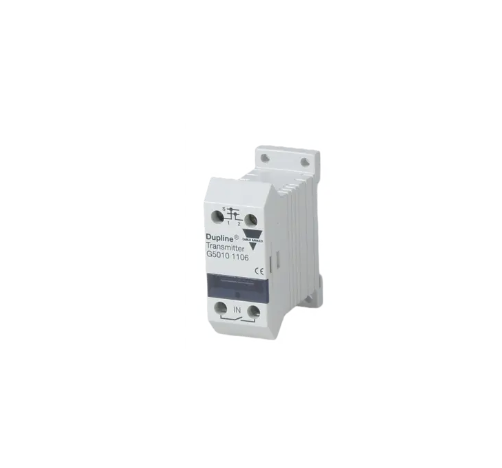
-
 peter
Hi there! Welcome to my shop. Let me know if you have any questions.
Your message has exceeded the limit.

Carlo Gavazzi Duplex fieldbus User Manual for Dual Channel Input Module G50102206
2025-06-15 21:44:48
Key Features
Number of channels: 2 independent inputs (channel 1+channel 2)
Input type (each channel can be independently configured):
Voltage mode: 0-10V DC
Current mode: 0/4-20mA (switched by jumper)
Communication protocol: RS-485 Modbus RTU (default baud rate 9600/19200/38400 bps, addresses 1-247)
Isolation level: 1500V AC isolation between input/communication/power supply
Wiring diagram (terminal definition)
Terminal number function description
1. 2 DC 24V power supply 1:+24V (18-30V DC), 2: GND
3-6 channel 1 signal 3: Ch1+, 4: Ch1-, 5: Shield (grounded)
7-10 channel 2 signal 7: Ch2+, 8: Ch2-, 9: Shield
11-12 RS-485 communication 11: A+, 12: B-
⚠️ Attention: The shielded wire must be grounded to suppress interference!
Jumper configuration (independent for each channel)
Jumper group position function
JP1 ON/OFF Ch1 signal type: ON=voltage, OFF=current
JP2 ON/OFF Ch2 signal type: ON=voltage, OFF=current
JP3 ON terminal resistor (only enabled for bus terminal module)
Modbus Register Mapping
Function Description of Register Address Data Type
30001 UINT16 channel 1 raw value (0-65535)
30002 Float Channel 1 scaled engineering value (calibration required)
30003 UINT 16 channel 2 raw value
30004 Float channel 2 scaled engineering value
Conversion formula (taking current mode as an example):
Actual value=(raw value/65535) × 20mA × range factor
Calibration steps (independent for each channel)
Zero calibration: Input 4mA (current mode) or 0V (voltage mode) → Read registers 30001 (Ch1)/30003 (Ch2) → Record as AD_Low
Full range calibration: Input 20mA or 10V → Record as AD-High
Set linear conversion in PLC:
plaintext
Engineering value=(current AD value - AD_Low) × (range upper limit - range lower limit)/(AD-High - AD_Low)+range lower limit
LED status diagnosis
Meaning of LED status
PWR green constant light power supply is normal
COM yellow flashing data communication
ERR red 2 times/second module internal error (restart check)
Red constant light communication timeout/address conflict
Troubleshooting
Phenomenon solution
Single channel no data check jumper settings → Measure input terminal voltage/current → Verify sensor power supply
Unstable communication, enable terminal resistor JP3 → check A+/B polarity → reduce baud rate
Data jump signal line with magnetic ring → single point grounding of shielding layer → away from frequency converter cable
Tags: Carlo Gavazzi Duplex fieldbus, Input Module, G50102206

