Carlo Gavazzi Duplex fieldbus User Manual for Single Channel Input Module G50101106
Core functions
Input type: Supports single channel 0-10V DC or 0/4-20mA analog signal input (switched through jumper).
Applicable sensors: standard industrial signal sources such as temperature transmitters, pressure sensors, flow meters, etc.
Output communication: Data is usually transmitted through RS-485 Modbus RTU protocol (with controller or PLC).
Installation and wiring
Power connection:
Terminal 1 (+V): Positive pole of DC 24V power supply (range 20-30V DC).
Terminal 2 (GND): Negative pole of power supply.
Signal input:
Terminal 3 (IN+): Signal positive pole (voltage/current input).
Terminal 4 (IN -): Signal negative terminal (common terminal).
Communication interface:
Terminal 5 (A+)/6 (B -): RS-485 bus (A+connected to positive, B - connected to negative).
Shielded terminal: grounded to reduce interference.
⚠️ Attention: Disconnect the power supply before wiring to avoid short circuits!
Jumper settings (key configuration)
Function jumper position description
Signal type JP1 (ON/OFF) ON: Voltage mode (0-10V)
OFF: Current mode (0/4-20mA)
Terminal resistor JP2 (ON/OFF): Set the bus terminal module to ON and the rest to OFF
LED indicator light status
Meaning of LED status
PWR green constant light power supply is normal
COM yellow flashing data communication
ERR red constant light/flashing power error/communication failure
Modbus Register Configuration
Register Address Function Data Format
30001 channel raw value 16 bit integer (0-65535)
30002 scaled engineering value floating-point number (to be calibrated)
Example: If 10V is input, the value of register 30001 is approximately 65535.
Calibration steps
Input 0% range signal (such as 0mA), record the value of register 30001 → AD_Low.
Input a 100% range signal (such as 20mA) and record the value → AD-High.
Set linear scaling formula in the controller:
Engineering value=(current AD value - AD_Low) × (range upper limit - range lower limit)/(AD-High - AD_Low)
Common problem handling
Problem troubleshooting steps
No signal input check jumper mode → Confirm sensor power supply → Measure terminal 3-4 voltage/current
Confirm terminal resistance for communication interruption → Check A+/B polarity → Test bus impedance
Check grounding for large data fluctuations → keep signal lines away from strong electrical cables → add RC filters

Recently Posted
-
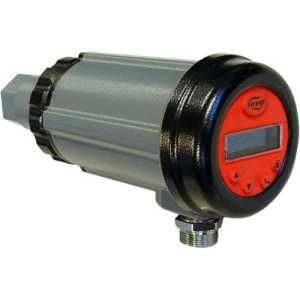
The STONEL QX Series: Explosionproof Limit Switch for the Most Hazardous Process Environments
April 29, 2026The STONEL QX Series: The Ultimate Explosionproof Limit Switch for Div. 1/Zone 1 Hazardous AreasIntroduction: The Critical Role of Read More
 -
The Complete Guide to STONEL QN Series Position Monitors: Compact, Versatile, and Built for Hazardou
April 29, 2026The Complete Guide to STONEL QN Series Position Monitors: Compact, Versatile, and Built for Hazardous EnvironmentsIn process autom
Read More -
The Complete Technical Guide to STONEL EN Series Position Switches: Model Decoding, Specifications,
April 29, 2026The Complete Technical Guide to STONEL EN Series Position Switches: Model Decoding, Specifications, Applications & Industrial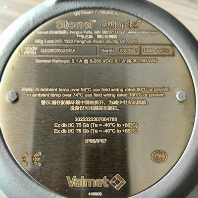 Read More
 -
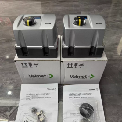
Valmet ND9206HE1T-K2-A3-DS04 Valve Positioner: Smart Digital Control for Advanced Process Automation
April 23, 2026Valmet ND9206HE1T-K2-A3-DS04 Valve Positioner: Smart Digital Control for Advanced Process AutomationIn modern industrial environme Read More

Contact Us
Recommended Products
-
 Metso Pneumatic Actuator VPVL100SR6BDNegotiableMOQ: 1 Piece
 -
Metso Locator ND9206HE1T-K2-A3-DS04NegotiableMOQ: 1 Piece
-
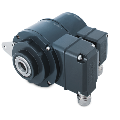
Baumer Encoder HOG10 DN1024 I LR 16H7 KLK-AXNegotiableMOQ: 1 Unit
-
ABB Flame Detectors QDDMEE20GP and SF810-UV-3000NegotiableMOQ: 1 Unit
-
STONEL Position SwitchQX2VCR02HRA, QN4XD05HRA, EN33A05DMNegotiableMOQ: 1 Unit
-
STONEL Position SwitchQX35CR05SRA,QX35K05SDM ,QN45CK02HDMNegotiableMOQ: 1 Unit
-
ABB Pneumatic Actuator LP10BB10010+locator V18345-2020521001 Complete SetUS$ 3500MOQ: 1 Set
-
ABB Excitation Filter Screen 3BHL001141P0002US$ 112MOQ: 1 Blade
-
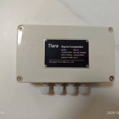
Tiara DSC-18 Digital Signal ComparatorUS$ 450MOQ: 1 Unit
-
GE 362A1052P104 Flame DetectorNegotiableMOQ: 1 Unit

-
GE IC698CRE030 RX3i PACSystem CPUNegotiableMOQ: 1 Unit
-
ABB LP10BB10010 Pneumatic ActuatorNegotiableMOQ: 1 Unit
-
ABB LP32BB10 Pneumatic ActuatorNegotiableMOQ: 1 Unit
-
ABB WSFAN230 Cooling Fan (P/N: 68442966)US$ 1200 - 2000MOQ: 1 Unit
-
GE Multilin 869 Motor Protection Relay Model 869-E-P1-NN-G1-L-S-N-A-A-N-M-S-P-F-B-SE-N-N-B-4 - Complete Technical OverviewUS$ 11000 - 15000MOQ: 1 Unit
-
Fireye 95UVS4-1WINC: Next-Generation Digital UV Flame SafetyUS$ 4400 - 5500MOQ: 1 Unit
-
Fireye 95DSS3-1WINC Ultraviolet (UV) Flame ScannerUS$ 5300 - 6500MOQ: 1 Unit
-
STONE Position Switch QX35CR05SRAUS$ 600 - 1000MOQ: 1 Unit
-
ABB Bailey Power Supply PHARPS32200000: A Reliable 320W System Power Module for Critical Industrial ApplicationsUS$ 3000 - 5000MOQ: 1 Unit
-
ABB PHARPSCH100000 Redundant Power ChassisNegotiableMOQ: 1 Unit