
Step-by-Step Installation Guide for the DT01 Fieldbus Terminal Module
Step-by-Step Installation Guide for the DT01 Fieldbus Terminal Module
The Carlo Gavazzi DT01 is a reliable fieldbus terminal module designed for Dupline® systems, ensuring secure signal termination and optimal network performance. Whether you are setting up a new Dupline network or upgrading an existing system, proper installation of the DT01 is crucial for stability and signal integrity. This guide walks you through the entire installation process, offering practical tips for engineers, technicians, and system integrators.
1. Understanding the DT01 Module
Before installation, it’s essential to understand the purpose and components of the DT01 module:
Purpose: Acts as a termination module for Dupline fieldbus networks, preventing signal reflection and maintaining communication quality.
Key Features: Compact design, easy DIN-rail mounting, LED status indicators, and compatibility with various Dupline devices.
Connection Ports: Provides connection points for the fieldbus line and the last device in the chain.
2. Safety Precautions
Safety is paramount when working with fieldbus systems:
Power Off: Always switch off the Dupline network power supply before installation.
ESD Protection: Wear anti-static wrist straps to avoid damaging sensitive electronic components.
Proper Tools: Use insulated screwdrivers and proper mounting tools.
Follow Manufacturer Guidelines: Always adhere to Carlo Gavazzi’s technical documentation for the DT01 module.
3. Pre-Installation Checklist
Before mounting the DT01:
Verify module part number (DT01) and ensure it is compatible with your Dupline network.
Inspect the module for any physical damage.
Prepare DIN rails and ensure sufficient space for the module.
Check that fieldbus cables are of the correct type and length as per Dupline specifications.
4. Mounting the DT01 Module
DIN-Rail Installation:
Position the module on the DIN rail.
Press firmly until it clicks into place.
Ensure the module is secure and cannot move along the rail.
Spacing Considerations:
Maintain at least 5 mm spacing between modules to allow proper airflow.
Avoid mounting near heat sources or strong electromagnetic fields.
5. Connecting the Fieldbus Network
Identify Network End:
The DT01 should always be installed at the end of the Dupline fieldbus line.
Connect Fieldbus Cables:
Use the provided screw terminals to attach the incoming and outgoing fieldbus cables.
Ensure a firm connection; loose connections can cause communication errors.
Polarity Check:
Double-check the polarity of the cables according to Dupline wiring diagrams.
Tighten Screws:
Secure all terminal screws to avoid intermittent connections.
6. Powering Up and Testing
Restore power to the Dupline network.
Check the LED indicators on the DT01:
Green: Module operating correctly.
Red/Off: Possible wiring or network issues; recheck connections.
Perform a network scan using Dupline diagnostic tools to ensure proper communication with all modules.
7. Maintenance Tips
Periodically inspect connections for corrosion or loosening.
Keep the module free from dust and moisture.
Replace the module immediately if any signs of physical damage are observed.
8. Troubleshooting Common Issues
| Issue | Possible Cause | Solution |
|---|---|---|
| LED not lit | No power or improper connection | Check power supply and wiring |
| Intermittent signals | Loose terminals | Retighten all screws |
| Communication errors | Network not properly terminated | Ensure DT01 is at network end, polarity correct |
Conclusion
Proper installation of the DT01 fieldbus terminal module is essential for a reliable Dupline network. By following this guide, you can ensure efficient signal termination, minimize network errors, and extend the lifespan of your fieldbus system.
For more detailed product specifications and official manuals
Recently Posted
-
Valmet Spare Part Sets H132200 H026194 H098546 H108587 H136942 H120684 & Seat Rings 743880 743900
July 6, 2026Valmet Spare Part Sets H132200, H026194, H098546, H108587, H136942, H120684 and Seat Rings 743880, 743900: A Complete Guide to Rel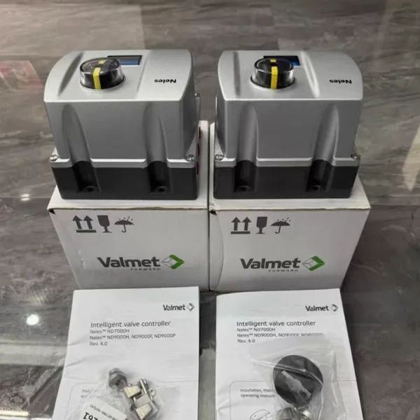 Read More
 -
ABB Flame Scanner Portfolio: A Technical Deep Dive into the SF810, FAU810, and UR600 Series for Mult
June 26, 2026Introduction: The Critical Role of Flame Detection in Industrial SafetyIn the high-stakes environment of industrial combustion—whe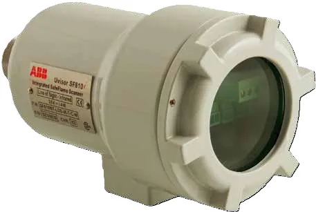 Read More
 -
How to Replace the Pneumatic Relay Assembly in Valmet Neles ND9000 Positioners
May 22, 2026How to Replace the Pneumatic Relay Assembly in Valmet Neles ND9000 PositionersIn critical flow control operations across the chemi
Read More -
ABB V18345-2020521001 Positioner with LP10BB10010 Pneumatic Actuator: Applications, Common Problems,
May 13, 2026ABB V18345-2020521001 Positioner with LP10BB10010 Pneumatic Actuator: Common Applications and Troubleshooting SolutionsIntroductio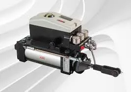 Read More

Contact Us
Recommended Products
-
 Metso Pneumatic Actuator VPVL100SR6BDNegotiableMOQ: 1 Piece
 -
Metso Locator ND9206HE1T-K2-A3-DS04NegotiableMOQ: 1 Piece
-
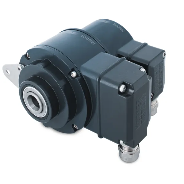
Baumer Encoder HOG10 DN1024 I LR 16H7 KLK-AXNegotiableMOQ: 1 Unit
-
ABB Flame Detectors QDDMEE20GP and SF810-UV-3000NegotiableMOQ: 1 Unit
-
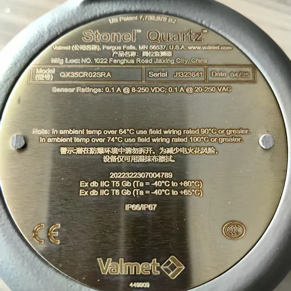
STONEL Position SwitchQX2VCR02HRA, QN4XD05HRA, EN33A05DMNegotiableMOQ: 1 Unit
-
STONEL Position SwitchQX35CR05SRA,QX35K05SDM ,QN45CK02HDMNegotiableMOQ: 1 Unit
-
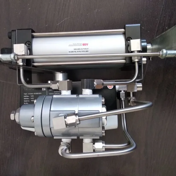
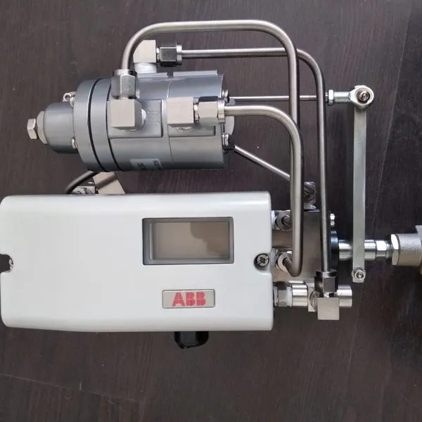
ABB Pneumatic Actuator LP10BB10010+locator V18345-2020521001 Complete SetUS$ 3500MOQ: 1 Set
-
ABB Excitation Filter Screen 3BHL001141P0002US$ 112MOQ: 1 Blade
-
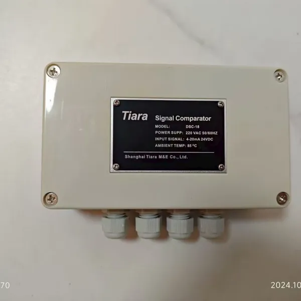
Tiara DSC-18 Digital Signal ComparatorUS$ 450MOQ: 1 Unit
-
GE 362A1052P104 Flame DetectorNegotiableMOQ: 1 Unit

-
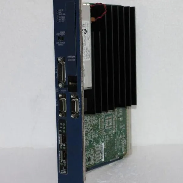
GE IC698CRE030 RX3i PACSystem CPUNegotiableMOQ: 1 Unit
-
ABB LP10BB10010 Pneumatic ActuatorNegotiableMOQ: 1 Unit
-
ABB LP32BB10 Pneumatic ActuatorNegotiableMOQ: 1 Unit
-
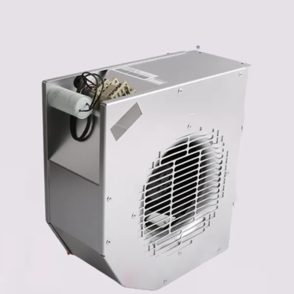
ABB WSFAN230 Cooling Fan (P/N: 68442966)US$ 1200 - 2000MOQ: 1 Unit
-
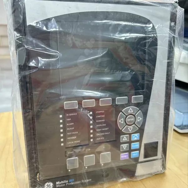
GE Multilin 869 Motor Protection Relay Model 869-E-P1-NN-G1-L-S-N-A-A-N-M-S-P-F-B-SE-N-N-B-4 - Complete Technical OverviewUS$ 11000 - 15000MOQ: 1 Unit
-
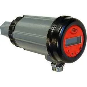
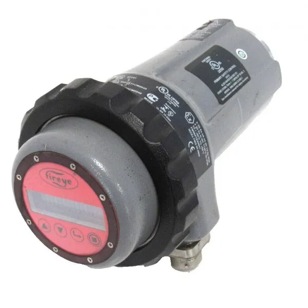
Fireye 95UVS4-1WINC: Next-Generation Digital UV Flame SafetyUS$ 4400 - 5500MOQ: 1 Unit
-
Fireye 95DSS3-1WINC Ultraviolet (UV) Flame ScannerUS$ 5300 - 6500MOQ: 1 Unit
-
STONE Position Switch QX35CR05SRAUS$ 600 - 1000MOQ: 1 Unit
-
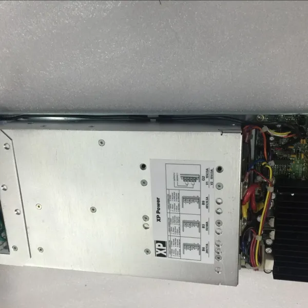
ABB Bailey Power Supply PHARPS32200000: A Reliable 320W System Power Module for Critical Industrial ApplicationsUS$ 3000 - 5000MOQ: 1 Unit
-
ABB PHARPSCH100000 Redundant Power ChassisNegotiableMOQ: 1 Unit